AHB-Lite Multi-Layer Interconnect Switch
Parameterised AHB-Lite Multi-layer Interconnect Switch
License Terms:
Non-Commercial License
Project maintained by:

Datasheet: AHB-Lite Multi-Layer Interconnect Switch

Contents
Introduction
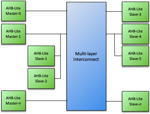
The Roa Logic AHB-Lite Multi-layer Interconnect Switch, hereafter referred to as ’the Interconnect’, is a fully parameterized high performance, low latency interconnect fabric soft IP for AHB-Lite. It allows a virtually unlimited number of AHB-Lite bus masters and slaves to be connected without the need for bus arbitration to be implemented by the bus masters. Instead, slave side arbitration is implemented for each slave port within the core.
The Interconnect supports priority based and round-robin based arbitration when multiple bus masters request access to the same slave port. Typically arbitration completes within 1 clock cycle.
Features
-
AMBA AHB-Lite compatible
-
Fully parameterized
-
Unlimited number of bus masters and slaves1
-
Slave side arbitration
-
Priority and round-robin based arbitration
-
Slave port address decoding
-
Slave masking to increase system performance - New in v1.2
-
Error assertion when no slave correctly addressed - New in v1.3
Specifications
Functional Description
The Roa Logic AHB-Lite Multi-layer Interconnect is a highly configurable interconnect fabric for AMBA AHB-Lite based systems, enabling multiple masters to be connected to multiple slaves.
Connections are dynamically created based on which slave a master is addressing, and once created enable direct communication between master and slave without other masters being aware or interfering.
A new connection is typically created within one clock cycle, providing high bandwidth and low latency communication between master and slave.
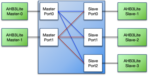
Master Port
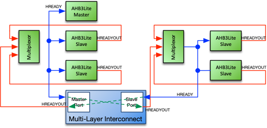
An AHB-Lite bus master connects to a master port of the Multi-layer Interconnect. The master port is implemented as a regular AHB-Lite slave interface thereby allowing support for complex bus structures.
The following figure shows an example bus structure where a bus master – Master-1 – has two directly connected slaves; the Interconnect-Master-Port1 and Slave-4
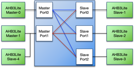
To access a slave, the Interconnect first checks if the designated slave port is available. If it is available the slave port immediately switches to the requesting master. If the slave port is occupied due to another master accessing the slave, the master port generates wait states until the requested slave becomes available. Note the pipelined nature of the AHB-Lite bus may cause a single wait state to be inserted when the slave switches to a new master.
The slave port always retains the connection to the master until another master requests access to that slave port; this enables the original master to request further access to the slave without incurring any delay due to arbitration.
Master Priority
Each master port has a priority level port (mst_priority[ ]).
When multiple masters with different priority levels request access to the same slave port, access is always granted to the master with the highest priority level. If a new master requests access while a transaction is already in progress, access will be granted according to its priority, ahead of any waiting lower priority masters. If masters have the same priority level, then access is granted based on a round-robin scheme.
Master priority may be set dynamically, however assigning a static
priority results in a smaller Interconnect and reduces timing paths. The
priority value may only be changed while the master port is idle; i.e.
mst_HSEL is negated (‘0’) and/or when mst_HTRANS is IDLE.
Bus Locking Support
The priority levels determine the order in which masters are granted
access to the slave port. The slave port switches between masters when
the current accessing master is idle (mst_HSEL is negated and/or
mst_HTRANS = IDLE) or when the current burst completes.
However the current master may lock the bus by asserting HMASTLOCK;
this prevents the slave port switching.
Specifying the number of Master Ports
The number of master ports is specified by the MASTERS parameter.
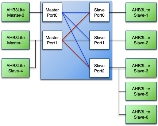
Slave Port
An AHB-Lite bus slave connects to a slave port of the Multi-layer Interconnect. The slave port is implemented as a regular AHB3-Lite master interface thereby allowing support for complex bus structures such as shown below:
Address Space Configuration
Each slave port has an address base (slv_addr_base) and address mask
(slv_addr_mask) port. Together these set the address range covered by
the slave port.
The address base port specifies the base address for the address range
covered by the slave port and the address mask port defines the address
range covered by the slave port. The internal port select signal is
specified as slv_addr_base AND slv_addr_mask.
The address base and address mask values may be changed dynamically, however assigning static values results in a smaller Interconnect and reduces timing paths. Address base and address mask may only be changed when the slave port(s) are idle. Since multiple masters may be active at the same time trying to access the interconnect, special care must be taken to ensure no master accesses the Interconnect while updating the address base and address mask values.
The slave port asserts HSEL when accesses are within the port’s
address range. When the port is not being accessed HSEL is negated
(‘0’), but HTRANS and other AMBA signals will still provide data.
These signals must be ignored while HSEL is negated (‘0’).
The slave port will output the full address, i.e. all HADDR_SIZE bits,
on its address bus (slv_HADDR). Connected AMBA slaves should use the
relevant least significant bits (LSBs) only.
Example 1
slave_addr_base = 32'h1000_0000
slave_addr_mask = 32'hF000_0000
Address-range = 32'h1000_0000 to 32'h1FFF_FFFF
Example 2
slave_addr_base = 32'h4000_0000
slave_addr_mask = 32'hE000_0000
Address-range = 32'h4000_0000 to 32'h5FFF_FFFF
Slave Port HREADYOUT and HREADY Routing
The slave port has an HREADYOUT port, which is not part of the
AHB-Lite specification. It is required to support slaves on the master’s
local bus. The HREADY signal, generated by the multiplexor on the
master local bus, drives the addressed slave’s HREADYOUT port.
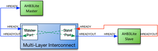
The simple case of where only one master is connected to a master port or where only a single slave is connected to a slave port is illustrated below.
There are no multiplexors on either the master bus or the slave bus.
Since there is no other slave on the master bus, its HREADY signal is
only driven by the master port’s HREADYOUT signal. Thus the master
port’s HREADYOUT drives both the master’s HREADY input and the
master port’s HREADY input.
Similarly since there is no other slave on the slave bus, the slave
port’s HREADYOUT signals drives the slave’s HREADY input and the
slave’s HREADYOUT signal drives the slave port’s HREADY input.
Specifying the number of Slave Ports
The number of slave ports is specified by the SLAVES parameter.
Configuration
Introduction
The Roa Logic AHB-Lite Multi-layer Interconnect is a highly configurable interconnect fabric for AMBA AHB-Lite based systems. The core parameters and configuration options are described in this section.
Core Parameters
| Parameter | Type | Default | Description |
|---|---|---|---|
HADDR_SIZE |
Integer | 32 | Address bus size |
HDATA_SIZE |
Integer | 32 | Data bus size |
MASTERS |
Integer | 3 | Number of master ports |
SLAVES |
Integer | 8 | Number of slave ports |
SLAVE_MASK[MASTERS] |
Array | All ’1’s | Mask slaves accessible by each master |
ERROR_ON_SLAVE_MASK[MASTERS] |
Array | inv(SLAVE_MASK) |
Enable error reporting for masked slaves |
ERROR_ON_NO_SLAVE[MASTERS] |
Array | All ’0’s | Disable error reporting when non-mapped address space accessed (to match previous IP releases) |
Table 1: Core Parameters
HADDR_SIZE
The HADDR_SIZE parameter specifies the width of the address bus for
all master and slave ports.
HDATA_SIZE
The HDATA_SIZE parameter specifies the width of the data bus for all
master and slave ports.
MASTERS
The MASTERS parameter specifies the number of master ports on the
interconnect fabric.
SLAVES
The SLAVES parameter specifies the number of slave ports on the
interconnect fabric.
SLAVE_MASK[ ]
The SLAVE_MASK[ ] parameter determines if a master may access a slave.
Defining which master may access individual slaves (rather than allowing
all masters to access all slaves) may significantly reduce the logic
area of the interconnect and improve overall performance.
There is one SLAVE_MASK parameter per master, each SLAVES bits wide.
i.e. SLAVE_MASK[ ] is an array of dimensions MASTERS x SLAVES.
Setting a SLAVE_MASK[ ] bit to ’0’ indicates that master cannot access
the slave. Conversely, setting a SLAVE_MASK[ ] bit to ’1’ indicates
that master may access the slave.
ERROR_ON_SLAVE_MASK[ ]
The ERROR_ON_SLAVE_MASK[ ] parameter enables generating an AHB error
response when the master attempts to access a masked slave port.
There is one ERROR_ON_SLAVE_MASK parameter per master, each SLAVES
bits wide. i.e. ERROR_ON_SLAVE_MASK[ ] is an array of dimensions
MASTERS x SLAVES.
Setting an ERROR_ON_SLAVE_MASK[ ] bit to ’0’ indicates that an AHB
error response will not be generated if the master is masked from
accessing the corresponding slave. Conversely, setting a
ERROR_ON_SLAVE_MASK[ ] bit to ’1’ indicates that an AHB error response
will be generated if the master is masked from accessing the
corresponding slave.
The default value of ERROR_ON_SLAVE_MASK[ ] is the bitwise inverse of
SLAVE_MASK[ ] - i.e. inv(SLAVE_MASK[ ]). If SLAVE_MASK[ ] is
assigned a value, then ERROR_ON_SLAVE_MASK[ ] is by default
inv(SLAVE_MASK[ ]). The default value of inv(SLAVE_MASK[ ]) causes
the core to generate an error response when a masked slave is addressed
by a master.
ERROR_ON_NO_SLAVE[ ]
The AHB-Lite Multi-layer Interconnect uses slv_addr_base and
slv_addr_mask to decode the target slave port. It can therefore
determine if a master attempts to access a non-mapped slave port. This
means the switch can generate an AHB error response should a master
attempt to access an address which is not mapped to any slave port.
The ERROR_ON_NO_SLAVE[ ] is a is MASTERS bits wide parameter used to
enable error response generation for this scenario. Setting a bit of the
parameter to ’1’ enables error generation for the corresponding master.
The default value for ERROR_ON_NO_SLAVE[ ] is all bits set to ’0’,
disabling this feature to match the behaviour of previous releases of
the IP.
Core Macros
| Macro | Description |
|---|---|
RECURSIVE_FUNCTIONS_SUPPORTED |
Enable use of recursive functions |
Table 2: Core Macros
RECURSIVE_FUNCTIONS_SUPPORTED
Recursive functions and modules are used within the verilog source code. However EDA tools vary in their support for recursion, with some supporting recursive functions, whereas others support recursive modules or both. For example, Intel Quartus v19.1 and earlier supports recursive modules, but not recursive functions.
To accomodate these toolchain differences, recursive modules are the
default method used for implementation. However recursive functions may
instead be enabled by setting the synthesis macro
RECURSIVE_FUNCTIONS_SUPPORTED
Interfaces
Global Signals
The common signals are shared between all devices on the AHB bus. The AHB-Lite Interconnect has master and slave AHB-Lite buses and they all use the global signals.
| Port | Size | Direction | Description |
|---|---|---|---|
HRESETn |
1 | Input | Asynchronous active low reset |
HCLK |
1 | Input | System clock input |
Table 3: AMBA3 Global Signals
HRESETn
When the active low asynchronous HRESETn input is asserted (‘0’), the
core is put into its initial reset state.
HCLK
HCLK is the system clock. All internal logic operates at the rising
edge of the system clock. All AHB bus timings are related to the rising
edge of HCLK. All master and slave ports must operate at the same
HCLK clock.
Master Interface
The master ports are regular AHB3-Lite slave interfaces. All signals are supported. See the AHB-Lite specifications for a complete description of the signals. In addition, a custom master priority port is included per interface to enable prioritisation when multiple masters attempt to simultaneously access the same slave. This prioritisation may be defined statically or dynamically changed during operation.
The AHB-Lite Multi-layer Interconnect implements 1 or more interfaces to
AHB-Lite masters as defined by the MASTERS parameter. Therefore the
following signals are all arrays reflecting the number of masters
supported.
| Port | Size | Direction | Description |
|---|---|---|---|
mst_HSEL |
1 | Input | Bus select |
mst_HTRANS |
2 | Input | Transfer type |
mst_HADDR |
HADDR_SIZE |
Input | Address bus |
mst_HWDATA |
HDATA_SIZE |
Input | Write data bus |
mst_HRDATA |
HDATA_SIZE |
Output | Read data bus |
mst_HWRITE |
1 | Input | Write select |
mst_HSIZE |
3 | Input | Transfer size |
mst_HBURST |
3 | Input | Transfer burst size |
mst_HPROT |
4 | Input | Transfer protection level |
mst_HMASTLOCK |
1 | Input | Transfer master lock |
mst_HREADYOUT |
1 | Output | Transfer ready output |
mst_HREADY |
1 | Input | Transfer ready input |
mst_HRESP |
1 | Output | Transfer response |
Table 4: Master Interface AHB-Lite Port
| Port | Size | Direction | Description |
|---|---|---|---|
mst_priority |
clog2(MASTERS) |
Input | master priority Levels |
Table 5: Master Interface Custom Port
Note: clog2() refers to the System Verilog function by the same name, defined below, and is used to determine the required bitwidth of a bus required to represent the defined range of values:
The system function $clog2 shall return the ceiling of the log base 2 of the argument (the log rounded up to an integer value). The argument can be an integer or an arbitrary sized vector value. The argument shall be treated as an unsigned value, and an argument value of 0 shall produce a result of 0.
mst_HSEL
The master port only responds to other signals on its bus when
mst_HSEL is asserted (‘1’). When mst_HSEL is negated (‘0’) the
master port considers the bus IDLE and asserts HREADYOUT (‘1’).
mst_HTRANS
mst_HTRANS indicates the type of the current transfer. It is driven to
the connected slave.
| HTRANS | Type | Description |
|---|---|---|
| 00 | IDLE | No transfer required |
| 01 | BUSY | Connected master is not ready to accept data, but intents to continue the current burst. |
| 10 | NONSEQ | First transfer of a burst or a single transfer |
| 11 | SEQ | Remaining transfers of a burst |
Table 6: Transfer Type (HTRANS)
mst_HADDR
mst_HADDR is the address bus. Its size is determined by the
HADDR_SIZE parameter. It is driven to the connected slave.
mst_HWDATA
mst_HWDATA is the write data bus. Its size is determined by the
HDATA_SIZE parameter. It is driven to the connected slave.
mst_HRDATA
mst_HRDATA is the read data bus. Its size is determined by
HDATA_SIZE parameter. The connected slave drives it.
mst_HWRITE
mst_HWRITE is the read/write signal. mst_HWRITE asserted (‘1’)
indicates a write transfer. It is driven to the connected slave.
mst_HSIZE
mst_HSIZE indicates the size of the current transfer. It is driven to
the connected slave.
| HSIZE | Size | Description |
|---|---|---|
000 |
8bit | Byte |
001 |
16bit | Half word |
010 |
32bit | Word |
011 |
64bits | Double word |
100 |
128bit | |
101 |
256bit | |
110 |
512bit | |
111 |
1024bit | |
Table 7: Transfer Size Values (HSIZE)
mst_HBURST
The burst type indicates if the transfer is a single transfer or part of a burst. It is driven to the connected slave.
| HBURST | Type | Description |
|---|---|---|
000 |
SINGLE | Single access |
001 |
INCR | Continuous incremental burst |
010 |
WRAP4 | 4-beat wrapping burst |
011 |
INCR4 | 4-beat incrementing burst |
100 |
WRAP8 | 8-beat wrapping burst |
101 |
INCR8 | 8-beat incrementing burst |
110 |
WRAP16 | 16-beat wrapping burst |
111 |
INCR16 | 16-beat incrementing burst |
Table 8: Burst Types (HBURST)
mst_HPROT
The protection signals provide information about the bus transfer. They are intended to implement some level of protection. It is driven to the connected slave.
| Bit # | Value | Description |
|---|---|---|
| 3 | 1 | Cacheable region addressed |
| 0 | Non-cacheable region addressed | |
| 2 | 1 | Bufferable |
| 0 | Non-bufferable | |
| 1 | 1 | Privileged access |
| 0 | User access | |
| 0 | 1 | Data access |
| 0 | Opcode fetch | |
Table 9: Protection Signals (HPROT)
mst_HREADYOUT
When a slave is addressed, the mst_HREADYOUT indicates that the
addressed slave finished the current transfer. The Interconnect IP
routes the addressed slave’s HREADY signal to the master.
When no slave is addressed, the mst_HREADYOUT signal is generated
locally, inside the Interconnect.
mst_HMASTLOCK
The master lock signal indicates if the current transfer is part of a
locked sequence, commonly used for Read-Modify-Write cycles. While the
mst_HMASTLOCK is asserted, the Interconnect IP cannot switch the
addressed slave to another master, even if that master has a higher
priority. Instead the current master retains access to slave until it
releases mst_HMASTLOCK.
mst_HREADY
mst_HREADY indicates the status of the local HREADY on the master’s
local bus. It is routed to the HREADYOUT port of the connected slave.
mst_HRESP
mst_HRESP is the transfer response from the connected slave, it can
either be OKAY (‘0’) or ERROR (‘1’). The Interconnect IP routes the
connected slave’s HRESP port to mst_HRESP.
mst_priority
mst_priority is a custom port per master interface and defines the
priority of the attached master. The width of the bus is calculated as
clog2(MASTERS), with the lowest priority value defined as 0
and the highest priority being MASTERS-1.
For example, for a system with 4 masters the width of mst_priority
will be 2 bits to enable each master to have a unique prioritisation
level, with lowest priority being 0 and highest priority being 3.
Slave Interface
The slave ports are regular AHB-Lite master interfaces.. All signals are
supported. In addition each slave port has a non-standard
slv_HREADYOUT. See the AHB-Lite specifications for a complete
description of the signals.
The AHB-Lite Multi-layer Interconnect implements 1 or more interfaces to
AHB-Lite slaves as defined by the SLAVES parameter. Therefore the
following signals are all arrays reflecting the number of slaves
supported.
| Port | Size | Direction | Description |
|---|---|---|---|
slv_addr_base |
HADDR_SIZE |
Input | Slave base address |
slv_addr_mask |
HADDR_SIZE |
Input | Slave address space mask |
Table 10: Slave Interface Customisation Port
| Port | Size | Direction | Description |
|---|---|---|---|
slv_HSEL |
1 | Output | Bus select |
slv_HADDR |
HADDR_SIZE |
Output | Address |
slv_HWDATA |
HDATA_SIZE |
Output | Write data bus |
slv_HRDATA |
HDATA_SIZE |
Input | Read data bus |
slv_HWRITE |
1 | Output | Write select |
slv_HSIZE |
3 | Output | Transfer size |
slv_HBURST |
3 | Output | Transfer burst size |
slv_HPROT |
4 | Output | Transfer protection level |
slv_HTRANS |
2 | Input | Transfer type |
slv_HMASTLOCK |
1 | Output | Transfer master lock |
slv_HREADY |
1 | Input | Transfer ready input |
slv_HRESP |
1 | Input | Transfer response |
Table 11: Slave Interface AHB-Lite Port
slv_addr_base
slv_addr_base is a SLAVES sized array of addresses, each
HADDR_SIZE bits wide, defining the base address of each attached slave
device.
slv_addr_mask
slv_addr_mask is a SLAVES sized array of HADDR_SIZE bit wide
signals. Each slv_addr_base address is masked with the corresponding
slv_addr_mask value to define the addressable memory space of the
attached slave. Setting a bit of slv_addr_mask to ’0’ enables the
corresponding address bit.
See section ’Address Space Configuration’ for specific examples.
slv_HSEL
Slaves connected to the slave port must only respond to other signals on
the bus when slv_HSEL is asserted (‘1’). When slv_HSEL is negated
(‘0’) the interface is idle and the connected slaves must assert their
HREADYOUT (‘1’).
slv_HADDR
slv_HADDR is the data address bus. Its size is determined by the
HADDR_SIZE parameter. The connected master drives slv_HADDR.
slv_HRDATA
slv_HRDATA is the read data bus. Its size is determined by the
HDATA_SIZE parameter. It is driven to the connected master.
slv_HWDATA
slv_HWDATA is the write data bus. Its size is determined by the
HDATA_SIZE parameter. The connected master drives slv_HADDR.
slv_HWRITE
slv_HWRITE is the read/write signal. slv_HWRITE asserted (‘1’)
indicates a write transfer. The connected master drives slv_HWRITE.
slv_HSIZE
slv_HSIZE indicates the size of the current transfer. The connected
master drives slv_HSIZE.
| HSIZE | Size | Description |
|---|---|---|
000 |
8bit | Byte |
001 |
16bit | Half word |
010 |
32bit | Word |
011 |
64bits | Double word |
100 |
128bit | |
101 |
256bit | |
110 |
512bit | |
111 |
1024bit | |
Table 12: Data Transfer Sizes
slv_HBURST
The burst type indicates if the transfer is a single transfer or part of a burst. The connected master drives it.
| HBURST | Type | Description |
|---|---|---|
000 |
Single | Single access |
001 |
INCR | Continuous incremental burst |
010 |
WRAP4 | 4-beat wrapping burst |
011 |
INCR4 | 4-beat incrementing burst |
100 |
WRAP8 | 8-beat wrapping burst |
101 |
INCR8 | 8-beat incrementing burst |
110 |
WRAP16 | 16-beat wrapping burst |
111 |
INCR16 | 16-beat incrementing burst |
Table 13: Burst Types (HBURST)
slv_HPROT
The data protection signals provide information about the bus transfer.
They are intended to implement some level of protection. The connected
master drives slv_HPROT.
| Bit# | Value | Description |
|---|---|---|
| 3 | 1 | Cacheable region addressed |
| 0 | Non-cacheable region addressed | |
| 2 | 1 | Bufferable |
| 0 | Non-bufferable | |
| 1 | 1 | Privileged access. CPU is not in User Mode |
| 0 | User access. CPU is in User Mode | |
| 0 | 1 | Data transfer, always ‘1’ |
Table 14: Data Protection Signals
slv_HTRANS
slv_HTRANS indicates the type of the current data transfer.
| slv_HTRANS | Type | Description |
|---|---|---|
00 |
IDLE | No transfer required |
01 |
BUSY | Not used |
10 |
NONSEQ | First transfer of an data burst |
11 |
SEQ | Remaining transfers of an data burst |
Table 15: Data Transfer Type
slv_HMASTLOCK
The master lock signal indicates if the current transfer is part of a
locked sequence, commonly used for Read-Modify-Write cycles. The
connected master drives slv_MASTLOCK.
slv_HREADYOUT
The slv_HREADYOUT signal reflects the state of the connected master
port’s HREADY port. It is provided to support local slaves connected
directly to the master’s AHB-Lite bus. It is driven by the connected
master’s HREADY port.
Note: slv_HREADYOUT is not an AHB-Lite Signal.
slv_HREADY
slv_HREADY indicates whether the addressed slave is ready to transfer
data or not. When slv_HREADY is negated (‘0’) the slave is not ready,
forcing wait states. When slv_HREADY is asserted (‘0’) the slave is
ready and the transfer completed. It is driven to the connected master’s
HREADYOUT port.
slv_HRESP
slv_HRESP is the data transfer response, it can either be OKAY (‘0’)
or ERROR (‘1’). It is driven to the connected master.
Resources
Below are some example implementations when targeting the Altera Cyclone-V family of FPGAs. All implementations are push button, no effort has been undertaken to reduce area or improve performance.
| ↓ Res/Config → | 10x5 | 8x5 | 8x3 | 5x3 | 3x5 | 3x8 | 5x8 | 5x10 |
|---|---|---|---|---|---|---|---|---|
| ALM | 6438 | 4272 | 2927 | 1934 | 1753 | 2644 | 4522 | 5703 |
| Registers | 1220 | 926 | 842 | 533 | 338 | 377 | 668 | 725 |
| Fmax (MHz) | 47 | 61 | 68 | 71 | 109 | 104 | 66 | 63 |
Table 16: Resource Utilisation Examples
NOTE: Config in the above table refers to the MASTERS x SLAVES
configuration of the Interconnect.
Revision History
| Date | Rev. | Comments |
|---|---|---|
| 13-Oct-2017 | 1.0 | Initial release |
| 16-Sep-2019 | 1.1 | Add SLAVE_MASK[ ] parameter |
| 04-Nov-2020 | 1.2 | Add recursive function support |
| 13-Nov-2020 | 1.3 | Add ERROR_ON_NO_SLAVE[ ] parameter |
| 28-Dec-2023 | 1.3.1 | Correct mst_HRESP[ ] direction definition |
Table 17: Revision History
-
The number of bus masters and slaves is physically limited by the timing requirements. ↩